
The 1802 Namebadge
The 1802-Namebadge originally spawned out of my want for a colorful LED Nameplate for me to wear at 37C3. And originally, it was supposed to be a cheap, basic circuit using an Arduino and some dot-matrix displays.
However, feature-creep happened, and now it is a full microcomputer using the CDP1802 8-bit CPU, 2KiB of ROM and 2KiB RAM. The 4 dot-matrix-displays are driven using 5 external 8-bit registers that are memory-mapped into the CPU's memory bus.
Here’s a demo of the board in action:
Hardware
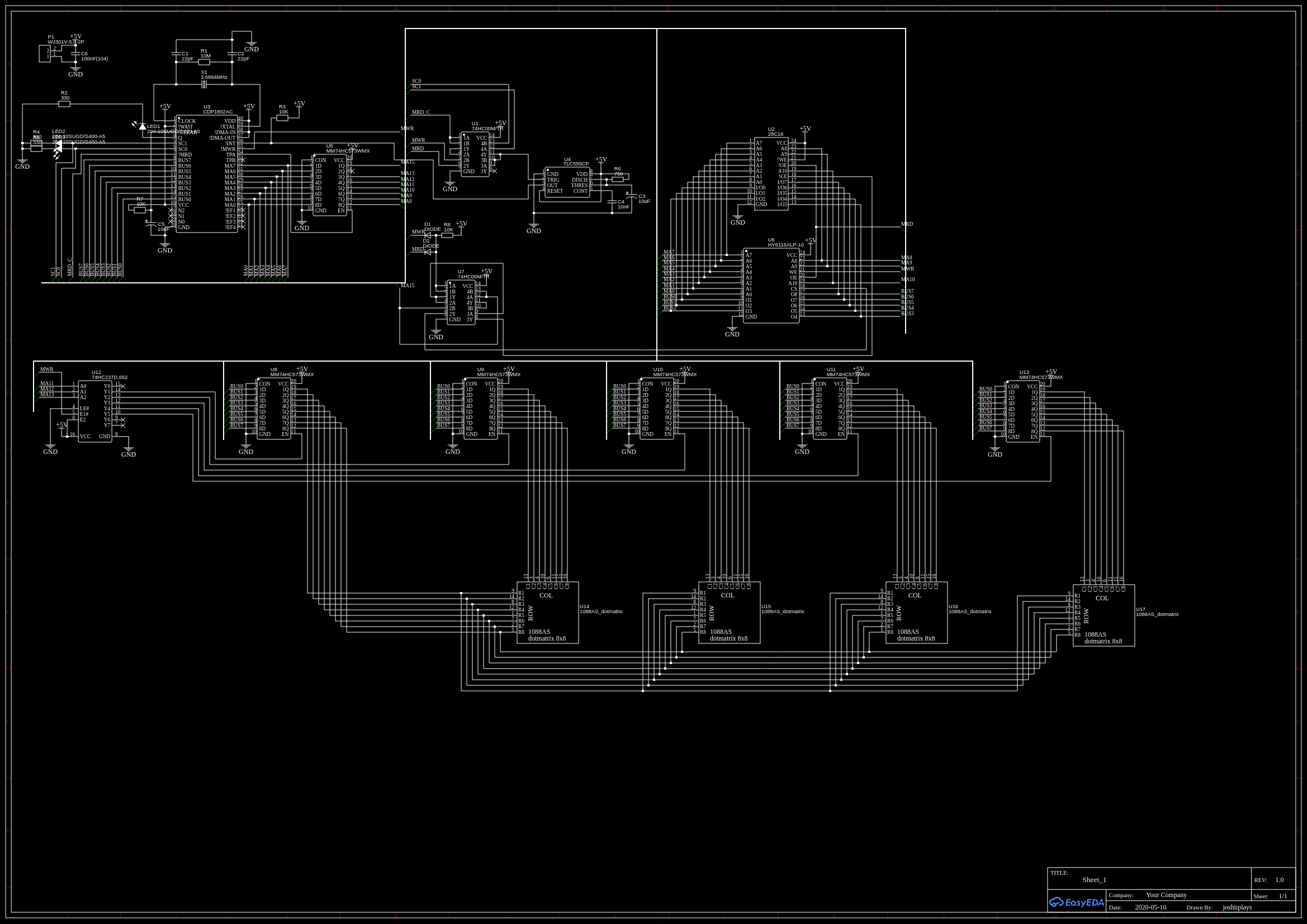
The displays are driven by a series of 5 8-bit latches mapped directly into the CPU’s address space. One holds the row selection, the other four the pixel data for that row. A de-multiplexer on three otherwise unused address lines is used for partial address decoding. This technically wastes a large amount of address space for driving the displays, but works here due to the low amount of memory used. The actual addresses used by the software are 1000h for row select, and 2000h, 3000h, 4000h and 5000h for pixel data. As there is no logic to de-select the regular memories when accessing the display registers, addresses overlapping with the ROM address space must be used to prevent accidental writes to RAM.
As multiplexing of the rows must be used to draw a full image, a fast interrupt generator is also present on the board in the form of a 555 timer. As the interrupt input of the 1802 is actually level-triggered (not edge-triggered), a astable oscillator cannot be used here, as it would trigger repeated interrupts. Instead, the 555 is configured in monostable mode, and reset using the CPU status signals indicating the beginning of an interrupt.
This ensures the circuit only triggers a single interrupt and that the time between interrupts is as consistent as possible.
The board features only one major hardware fault, which is the complete lack of resistors between the dot-matrix LED displays and 74-series ICs driving them. However, as both the anodes and cathodes of each display are connected to the output of an IC, and each row is only active for a short burst of time, this does not appear to have any damaging effects, and the current draws are within spec for the ICs used. However, it might be the cause for some rows appearing at a slightly different brightness compared to the others.
However, I also consider the memory organization on this system suboptimal. Really, I was being too optimistic with only giving it 2KiB of ROM. Although the text-scrolling program fits, the possibility of rendering more complex demos is very limited. I also could’ve made the board smaller. I really overestimated the amount of space required for traces.
Software
The assembly program consists of two main components. An interrupt that draws the contents of a RAM framebuffer onto the displays by going through all the lines of the display, switching to the next line on each interrupt and displaying the pixel data for it, and the main loop responsible for rendering the text.
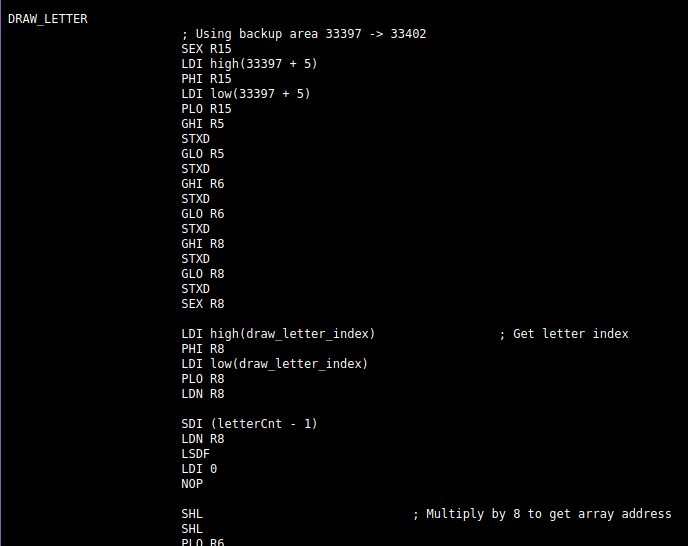
This is implemented using only three subroutines: one to draw a single letter into the framebuffer at a given position, one to draw a string with a given offset that uses the draw letter subroutine and finally a delay subroutine to adjust the text scroll speed.
A font containing all characters the code needs is stored in ROM. Each character in the font is only 6 pixels in width, counting the colum of empty pixels to the left of each character, used as padding. Only characters actually used are part of the font, so it is using a custom character encoding, instead of ASCII. A short Java script on my PC is used to convert any string into this format, which is then also stored in ROM.
The pixel data is stored in the framebuffer in the same format as is needed by the display registers, which 4 bytes per row, and each bit representing the state of one pixel, though the buffer actually holds 6 bytes per row with overscan on each side, to make the text rendering subroutines not have to worry about writing data outside the framebuffer when drawing characters that are cut of by either side of the display.
Text scrolling is accomplished by regularly increasing the pixel and character offsets of the string being drawn. Delay loops are inserted to control scroll speed. Interestingly, the CPU actually spends most of its time in idle loops, despite the fast interrupts and complex character rendering subroutine.
The full source-code for this project assembles into ~1.5KiB of raw binary, which fits nicely into the 2KiB ROM on the board. A zip file containing the source code and EasyEDA project files is available here: DL LINK
I also created a virtual version of this project for my VRChat avatar using my CDP1802 emulator shader. You can read about that here!