
Misc. Computer Systems
Not every microcomputer I build is worthy of a super-detailed page on my website. A lot are simple side projects, or too old for me to be able to talk about them much still.
Here is just a short compilation of them, in no particular order.
UB8840
I have a little bit of an obsession with chips fabbed in the GDR, before that whole industry collapsed there. The UB8840 is one of a series of "Einchipmikrorechner" (one chip microcomputers), which are just straight clones of Zilog Z8 parts.
Most of them use a mask ROM, which cannot be changed, but the UB8840 has some extra pins (for a total pin count of 64), breaking out the usually internal ROM address and data lines. This would’ve allowed development of code before sending it to the fab for mass-production in mask ROM parts.
In my case, I am using a custom PCB with an EEPROM on it also, and a single DL040 (74LS40 clone) as glue logic for the EEPROM enable signal.
The packaging of the UB8840 is quite cursed, with its staggered pins. Though it does make it very compact (much smaller than a 68000, which also has 64 pins).
The chip runs at a maximum of 8MHz and comes with a little under 128 bytes of RAM (some memory locations are special-purpose), GPIO lines, timers, a UART, and possibly an SPI port (haven’t tried it yet).
Its also very power hungry, getting noticably hot to the touch. I’ve begun to notice a bit of a trend with that from GDR ICs...
Other than that, there isn’t much more to say here, as this chip is otherwise a completely normal Z8 core.
I do like its instruction set, though. It has a high degree of orthogonality, which I usually desire in 8-bit CPUs.

Old Z80 Computer
This is the second microcomputer I ever built, years ago. Its fairly minimal, only having a Z80, 16KiB ROM, 2KiB RAM, 8 output ports and 8 input ports. It uses partial address decoding and because I didn’t understand the IO instructions of the Z80 at the time, the ports are memory-mapped. This is why there is so little space for memory.
However, only a single 74HC00 (and a couple diode-resistor ORs) are needed to implement the glue logic. There is also an AtMega32 on the board, for in-system ROM programming (which never worked, I always have to remove the Z80 for the programming to succeed).
The AtMega32 also generates the Z80’s clock and provides it with a serial output for printing text. The MCU detects writes to a specific memory location and then uses its own UART to send the written byte out to a console. There is no way to receive UART data this way.
This board, impressively, can run C programs compiled by z88dk, which is how I got it to bit-bang an SD card over the IO ports once and ray-traced a textured sphere.
Fun fact: the KiCad schematic for this board on the repo I had to create by beeping out the board with my multimeter. When I first built it, I went entirely by intuition and did not draw any schematics.
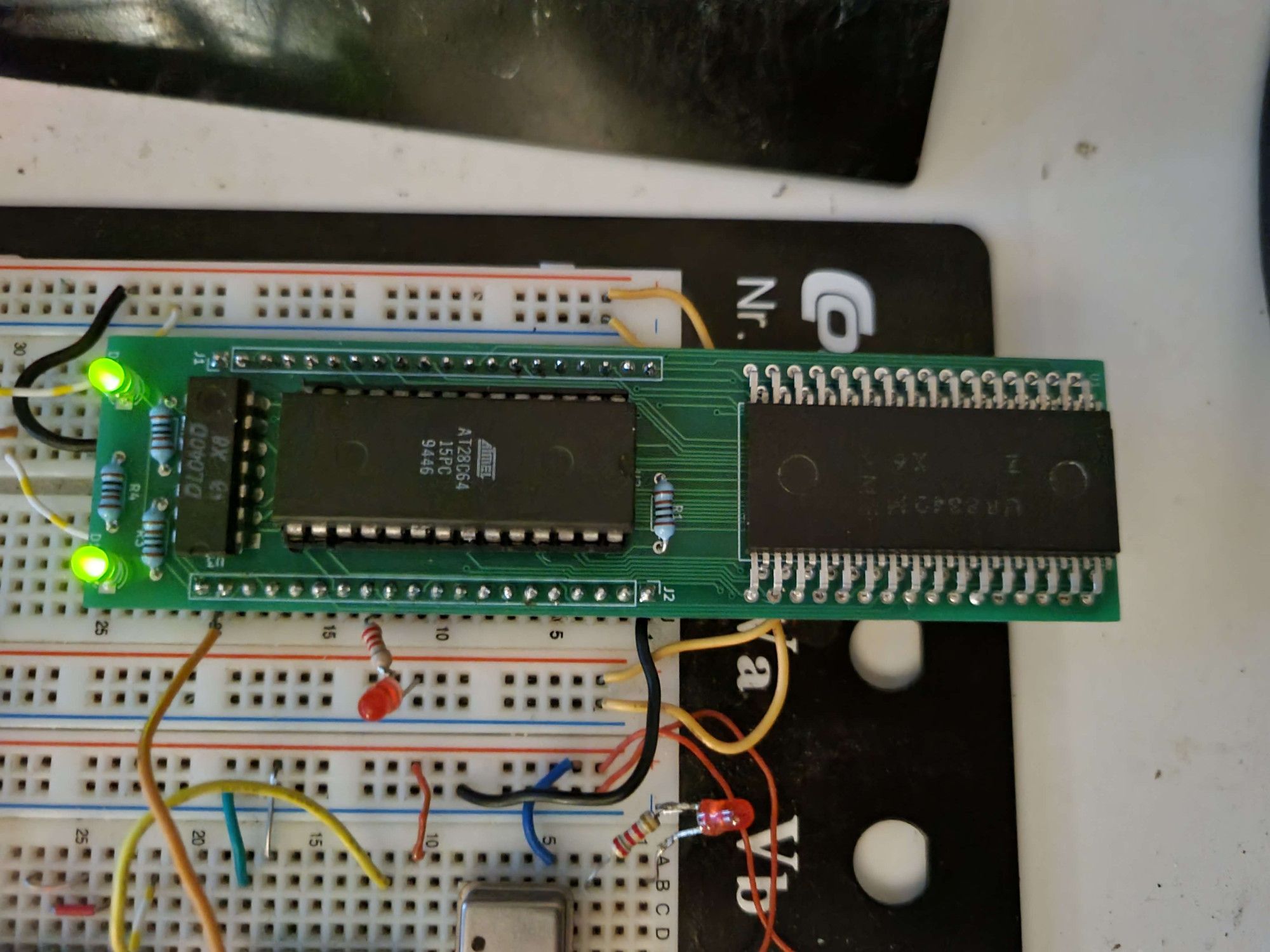
Z80 Tester
A little PCB in a similar style to my first Z80 computer, but a lot more sane. Output and Input ports are accessed by IO instructions, so there is space for up to 32KiB ROM this time, though the RAM IC is only 32 bytes.
Its not meant to be powerful anyways. I can pop Z80s into this to test/stress them a bit. The version of the board in the repo has the 7-segment display integrated on the PCB.
The standard test program uses this display to show the test state and to ask the user to trigger interrupts for it. Although I also wrote a quick program to use the display like a dice to roll random numbers.

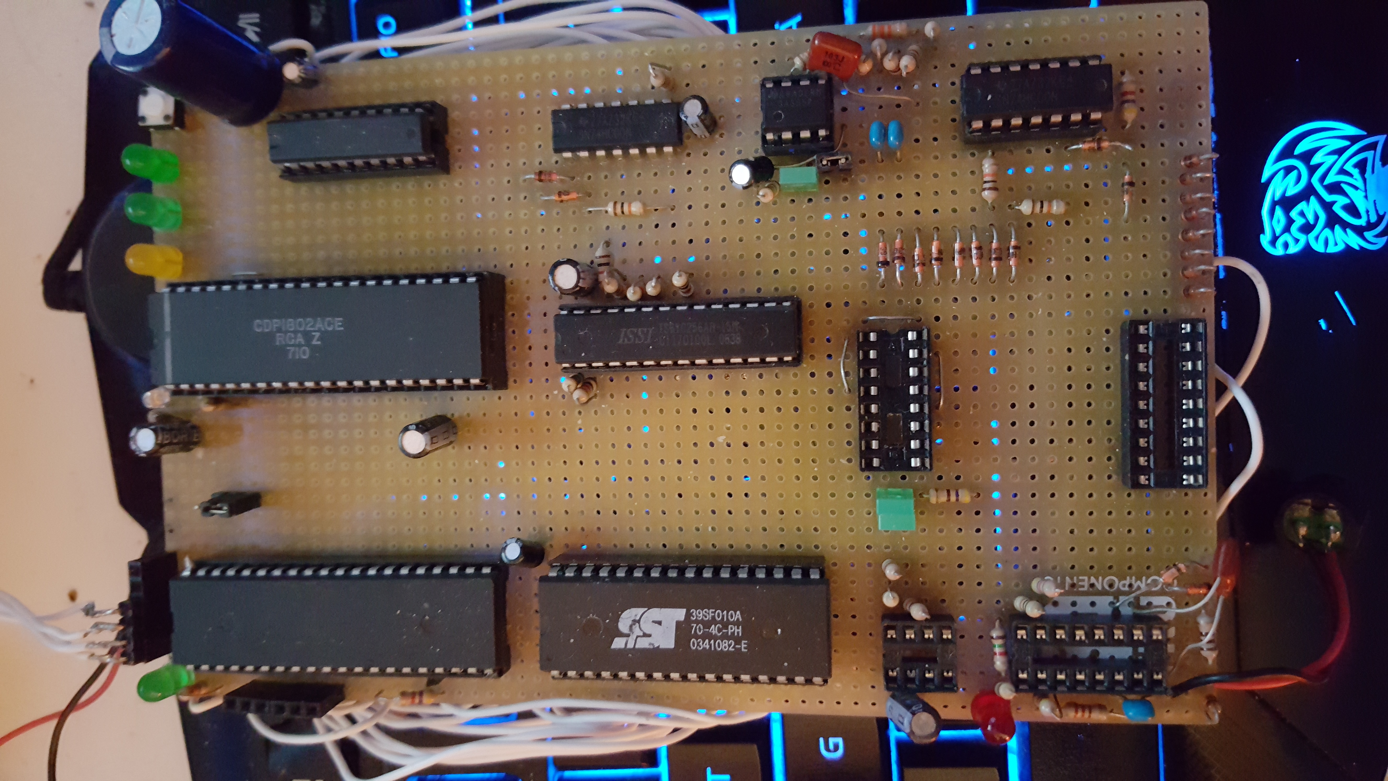
CDP1802 Computer
The very first microcomputer I ever built, so its not very good. 32KiB RAM, 32KiB ROM and same setup with an AtMega32 as the Z80 board. It also acts as an in-system ROM programmer that is also bugged and requires me to remove the CDP1802 to work and also works as a text output for the CPU.
At the bottom, you see where I tried to add some memory-mapped peripherals (simple tone output and a few output ports, I think), but failed because I didn’t build it correctly, and relied too much on diode resistor gates for it to be stable. This thing can also run C programs from the 1802 LCC build.
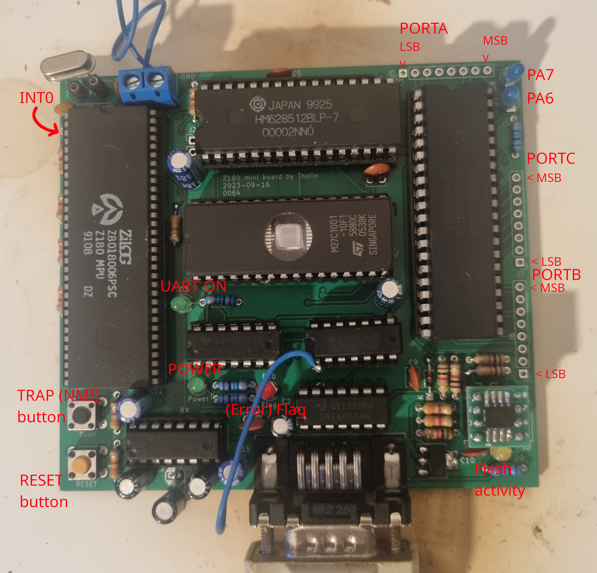
Z180 Mini Board
This computer is actually quite advanced on the software side, since I gave it a bunch of I/O ports specifically so it would be useful as a retro-ish Arduino substitute. The EPROM actually just contains a bootloader and the beginnings of the interrupt handlers.
The flash ROM in the lower-right corner holds the actual user program, technically making it possible for that software to be updated over the UART, though I’m still working on that.
Right now, the computer can be programmed in C, with a header file providing abstractions for the various pieces of I/O. This is the one computer on this list I’d recommend people to build for themselves as its just as useful as an Arduino for most purposes, but helps save chips from the e-waste pile.
As usual, hardware design files in the repo have already been updated and will not require bodge fixes anymore.
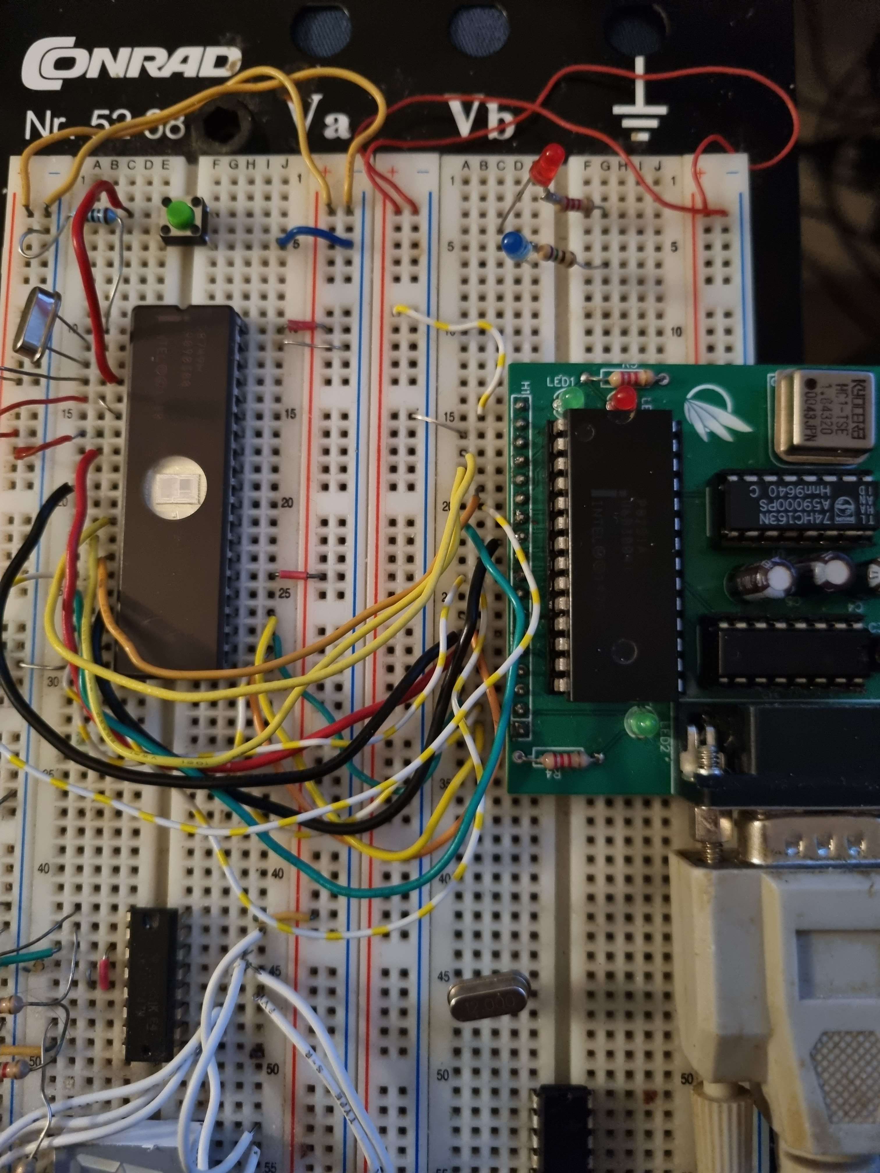
D8749
Another microcontroller, this time from Intel. Its a part of the almost forgotten MCS-48 line, which has a really odd instruction set that is missing some basic instructions such as subtraction (you may only add). That and the fact that conditional jump instructions only jump within the 256-byte page they reside in makes programming this thing a real challenge.
I did eventually manage to coax a mandelbrot set out of this one too, but it took some work.
This was originally going to have its own page on my website, titled something like 'The MCS-48 Experience', but it ended up not having a lot of substance, so I scrapped it.
But doesn’t it look pretty with the whole die visible? More ICs should be like this.
Also of note is that I still went through the effort of making an emulator in Verilog for this chip. You can find that and all the other stuff related to this computer in
its own repo.
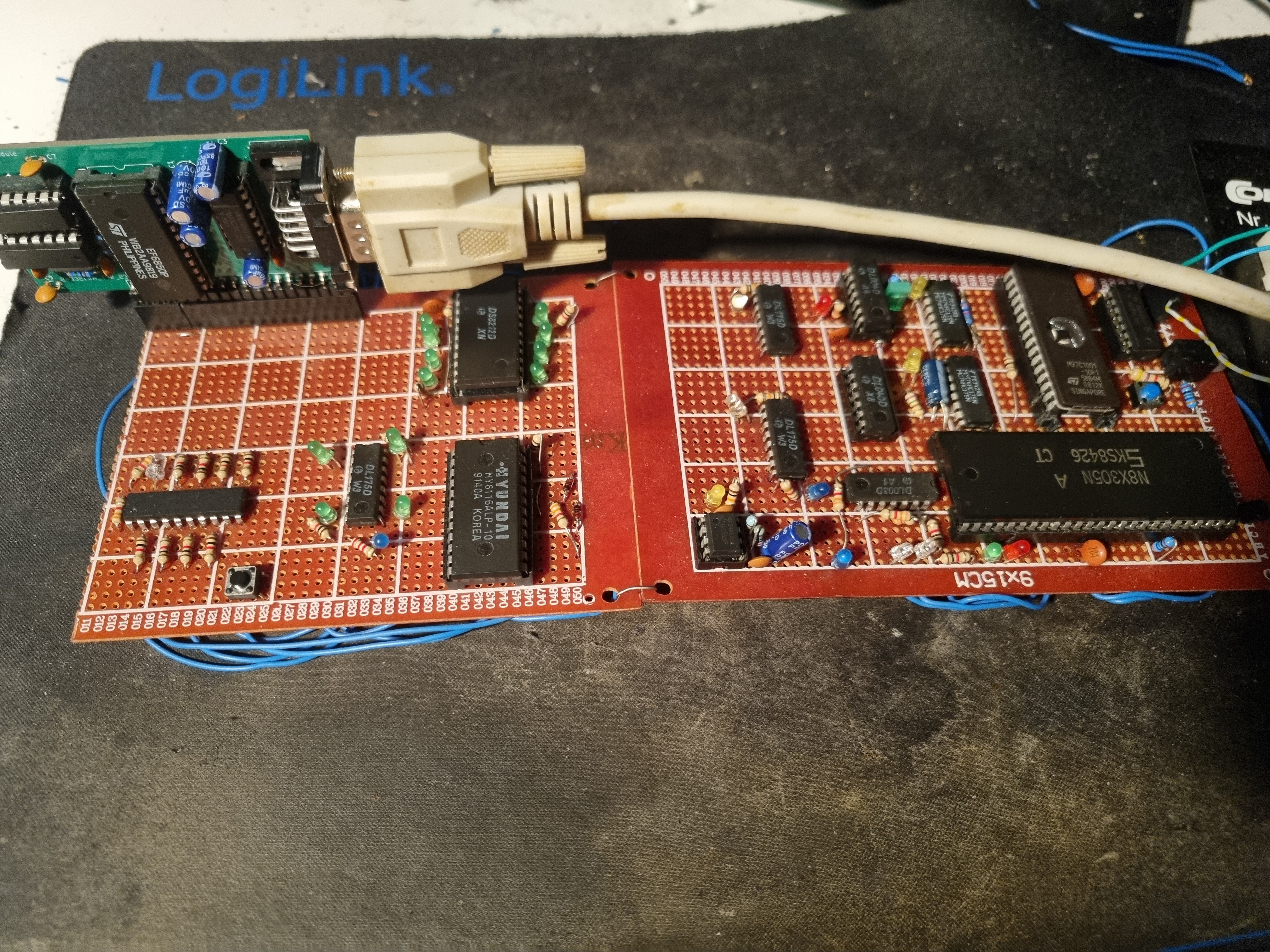
8X305
Probably the strangest 8-bit processor I’ve ever worked with. Its a Harvard Architecture microcontroller with separate instruction and data buses, but severely limited with its instruction set of just 8 instructions (though most have several addressing modes). It doesn’t even have a native understanding of RAM, only posessing a generic IO bus where one can attach a latch to buffer a memory address and then an actual SRAM memory.
Annoyingly, the datasheet uses 0 to denote the most significant bit and 7/15 the least significant and the IO bus lines are inverted (active low). Both of these caused me many problems. The 8X305 also requires 16-bit wide instructions and I had to invent a way to use a single 8-bit ROM by latching the lower half of each instruction on a specific CPU cycle where the timing requirements are particularly forgiving, and then merging that with the following 8 bits from the ROM for a full 16-bit instruction.
This architecture was absolutely just meant for signal processing, but I somehow still managed to coax my standard mandelbrot render out of it, though it cost me quite a bit of my sanity.

Ben Eater 6502 Compatible
Created to develop some extensions and code libraries for the Ben Eater 6502, this board is completely compatible with Ben Eater’s 65C02 homebrew up to (but not including) the SID videos. I liked the idea of making a homebrew computer with a little breadboard glued to the PCB, which eventually lead to this.
I did make some customizations, to try and make this computer as fast as possible, from the 15ns access time SRAM to the properly designed 4-layer PCB to reduce EMI interference. The only thing missing are the faster ACIA and VIA chips from WDC. I’ve also verified that this board works with a original MOS 6502.
It also features a string of addressable LEDs right on the PCB, but not wanting to sacrifice VIA port bits, they are instead wired to the ACIA’s DTR and RTS outputs, which, with some trickery, can be used as general-purpose outputs to bit-bang the first SK9822 LED’s serial port. It took a bit to work correctly as there is undocumented behavior of the ACIA. Clearing DTR and/or RTS (I never determined for which of the two this is true) in the command register may not immediately set the corresponding output pin high. If there is a value still shifting out of the Transmit Shift Register, the ACIA waits until this is done before updating the outputs. But I found workarounds to this, so communication to the LEDs is glitch-free.
Not only are the VIA ports broken out, but so is the data bus, some address lines and a chip-select signal from where the address decode is extended to allocate some addresses to any external device on the breadboard.

GitHub Repo
I created a single GitHub repo to contain the files for all the computers listed here. It has the hardware schematics and, if applicable, PCB designs, as well as a bunch of software for those boards.
To the repo