R6507 Single-Board Computer
This is a computer I built because I wanted to get some experience with an original 6502, not the 65C02 that is more popular nowadays. But, trying to obtain a original 6502 only got me re-labeled chips. Luckily, the 6507 exists, is way easier to obtain and literally is a 6502 with some pins removed. The dies of both chips are almost identical, with the exception of the removed connections for the unused pins, of course.
As an additional challenge, I tried to see if I could build this computer without the use of even a single DIP-40, which also helped in making it relatively small for what it can do. Just for fun, I also included a SN76489 for sound, and enough I/O to wire up a character LCD, or some SPI peripherals, which eventually expanded into having a 128 by 64 pixel LCD connected for graphics output.
Hardware
For memory, the 6507 is paired with a 128-byte RAM from Motorola I already had, and a 8KiB EEPROM. However, the 6507 can only address 8KiB of memory directly, so I needed to cut a chunk out of the EEPROM space for RAM and I/O. I wanted that piece to be as small as possible though, and also have both RAM and I/O overlap zeropage while also having the RAM mirrored into the stack page.
This made address decoding non-trivial, and is accomplished by a total of three 74-series logic chips, and some diode/resistor logic. A 1KiB segment is cut out of the beginning of EEPROM, making space for four mirrors of the same 50/50 split of a 256 byte range, where the first 128 bytes would go to I/O, and the second 128 bytes to RAM. This does mean that the first 1024 bytes of the ROM are wasted, and need to be programmed blank before the beginning of the program at address 1024, but does yield 7KiB of usable ROM space.
A brief mention of clock generation: the input clock is actually 20MHz, but is put through a 74-series counter for division, providing 10MHz (unused), 5MHz (for the SN76489), 2.5MHz (used in I/O) and 1.25MHz (for the CPU).
For I/O, then, I decided to use some more chips I had laying around and no other use for, which includes the SN76489, but also the three chips used for I/O. 16 bits of output port, and 8 bits of input port formed using DS8212s, which are east-german clones of the P8212 bus driver, which conveniently contains both latches and three-state drivers for the bus lines, meaning it can be used as either an input or output port.
Those GPIO ports are then used to drive all other hardware, including the SN76489. Originally, it was meant to be connected directly into the 6507’s bus, but for some reason, it didn’t work out on the first revision board. The timing did not work out, I guess. I believe that despite all the gate delays in its control lines, it still was too fast, and latched the garbage data that briefly appears on the 6507 bus before the real data during a write. This is something I side-stepped on the DS8212 output ports by ANDing their latch-enable lines with the 2.5MHz clock, meaning it would only engage exactly halfway through the write cycle.
Attached to the GPIO ports are also a character LCD display and, after some breadboard prototyping to confirm it would work, some SPI devices. I first tried experimenting with a serial flash ROM to get some more memory to store tracks to play on the SN76489, which worked beautifully. After that, I decided to get a bit more daring and connected a pixel LCD, which was surprisingly usable despite the memory constraints of the system.
I ended up making an expansion PCB to make hooking up these SPI peripherals easier, so those are now also 'official' parts of the SBC’s supported I/O.
Software
Finally having working hardware meant I could do what I wanted to in the first place, which is to code some 6502 assembly! Of course, most time was spent coding drivers for the various pieces of hardware, testing them, and applying ugly bodge fixes to the board, when things didn’t work out.
Finally, though, I did the thing I usually do, which is port my set of airthmetic subroutines for multiplication and division, and use them to implemented fixed-point maths for rendering the Mandelbrot set. I didn’t write too much additional software for this board yet, and if I do ever use it in a larger project, it’ll most likely only be as an oversized microcontroller.
If I had to rate my experience with 6502 assembly, I would call it 'mid', I guess. The simplicity of it means it was fast to pick up, but also quickly left me wanting more, instead of having to constantly deal with exchanging data with memory, and using ridiculous amounts of instructions to complete simple tasks. However, it is also difficult to argue with the fact that I managed to get into a flow state coding 6502 assembly much faster than some other 8-bit architectures I have worked with in the past.
Power
There is one major problem this SBC has that deserves its own section: power consumption! The board draws over 15W from the wall, and most of the chips get fairly warm. The DS8212s in particular suck power like crazy and get hot to the touch after just a few minutes. And transient spikes can get so high, plugging in the board triped the protection on my original power supply each time, and it usually took me several attempts just to power the computer up. Slightly over-volting the board to 5.3V fixed this issue however, and allowed me to push a slightly higher clock speed. Of course, at the cost of even more energy consumption. I would recommend not operating this board in a badly ventilated room.
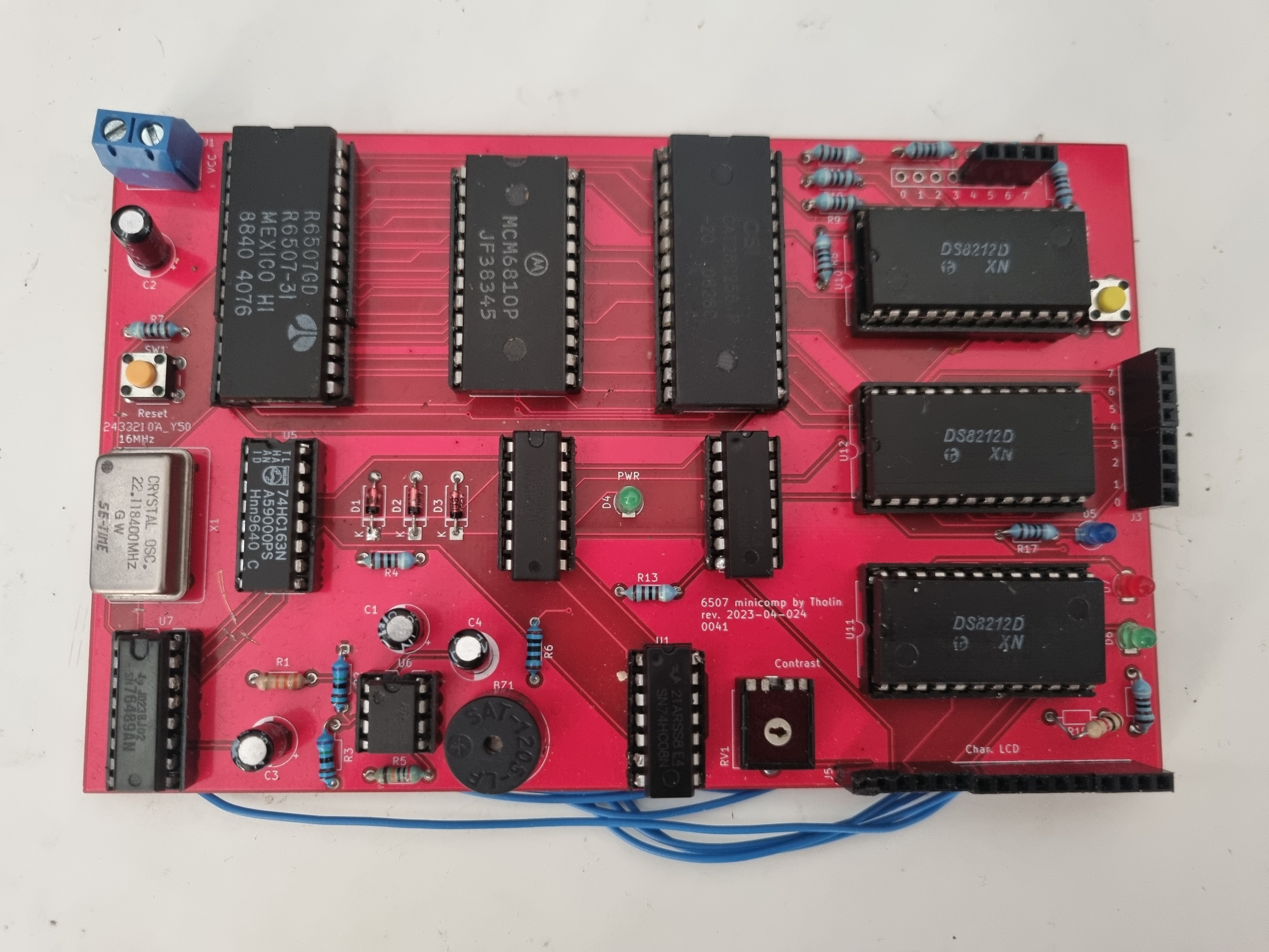
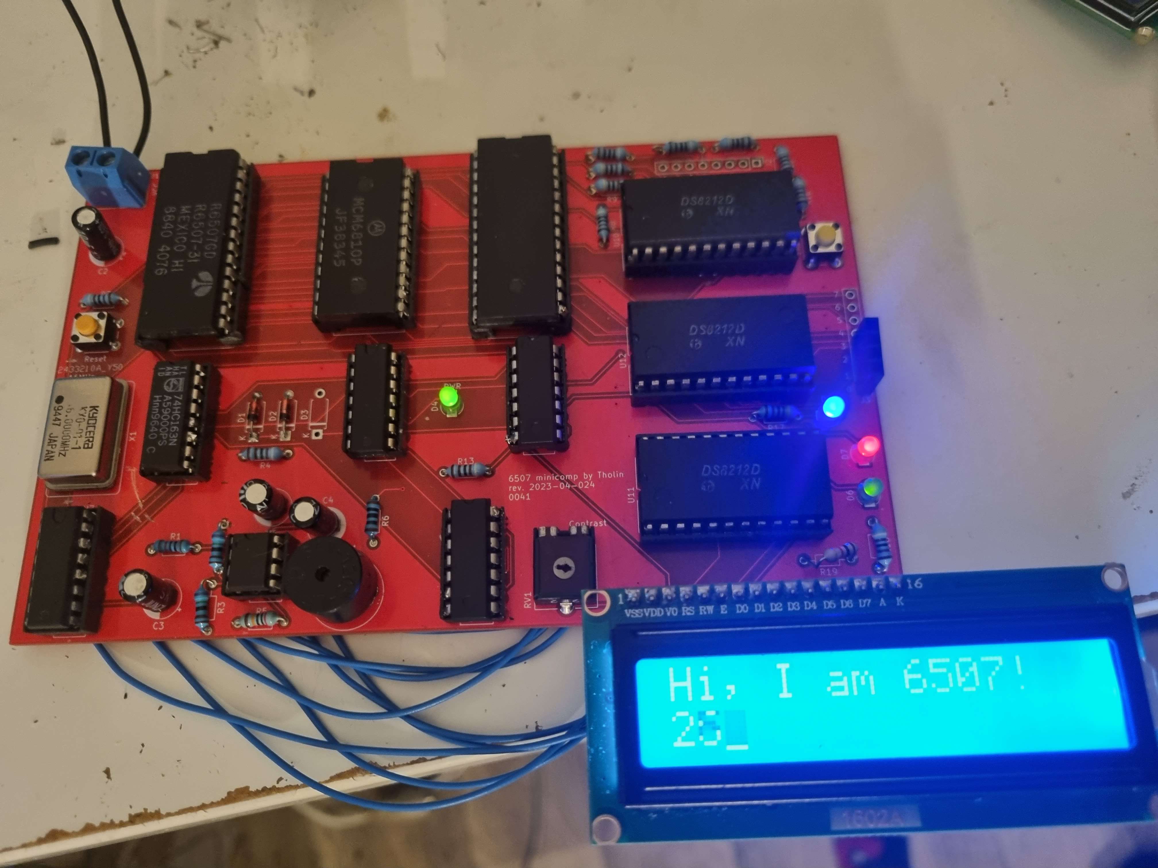
Pictures
Here are some picture of the final board. Note that these are of the first revision, which needed a lot of bodge fixes, and ended up requiring me to put the SPI expansion board on the wrong way around.
The version of the PCBs that is available on GitHub are of a second revision with all issues fixed, though I myself have yet to have the funds to put it together myself.
It should, however, work the exact same, as it is just the same as revision one, but with all my fixes baked-in.

Source files
If you wish to build a copy of this board for yourself (would recommend, it is still quite a fun little thing), I have made all the source files public! This includes schematics, PCB layouts and software I wrote for it.
View on GitHub